EBB`s Maxi Micra project
WARNING :
OBS : THIS THREAD WILL NOT OR CAN NOT BE CLOSED BY ” ED ” : ADMINISTRATOR FOR MSC FORUM IN UK !
IT IS A SHAME THAT SUCH A FANATASTIC COMMUNITY ARE CONTROLLED BY TOTALLY WRONG PEOPLE.
BELIVE ME ” ED ” ALL YOU ACCOMPLISH IS SHOWING OFF WHAT PERSON YOU REALY ARE 🙂
TO ALL YOU MICRA LOVERS OUT THERE ON MSC FORUM :
THIS PERSON IS MIXING HIS OWN PERSONAL INTEREST FOR THE SAKE OF THE FANTASTIC MICRA COMMUNITY AND THAT STINKS !
Other than that enjoy the Maxi Micra project 🙂
This project is presented in English , as the Micro Micra project is.
There has been so many Micra enthusiasts all over the world wanting me to gather together all the presented info on one location so her You can find the lot 🙂
Dette prosjektet blir presentert på engelsk av hensyn til alle Micra entusiaster rundt om i verden som har ønsket å få prosjekttråden samlet på ett sted derfor finner du den nå her 🙂
CHAPTER ONE : The beginning.
This project is going to be a little cars adventure from being a tiny little shy duckling to a roaring hawk that sheds fear amongst its prey. Ha Ha,,,,,doesn’t that sound weird ?
The Micra`s has made me more and more interested in what we can do with them and how they will perform after the stuff we did to them.
My “ Micro Micra “ project that you can read about here : http://www.micra.org.uk/threads/40020-EBBdude-s-Micro-Micra-project is just a simple way of doing small and easy stuff to get things better. That’s why its called “ Micro “ Micra. Micro,,,,as in Micro = little,,,small , tiny modifications.
“MAXI MICRA” project will go beyond little,,,in a hopefully big way as the project goes along its wild rocky road. This project will also look at some stuff regarding what one can try / do to get the car to handle and drive better,,,,a lot better and basically a h…..of a lot faster.
Anyone can boost up the pressure , buy zilions of e-bay high performance parts or make big buck power as a result of investing lost of parts and serious boost performance. Doing it the complete opposite way might not be as easy.
using almost only stock parts to modify is even trickier but i like challenges so why not 🙂
My goal is : As much percentage increasement of power as possible without buing tuning parts at all !
But enough talk , lets go straight to the start of this little adventure:
To quote the late Michal Jackson :
THIS IS IT :
![[IMG]](http://www.raceinfo.no/temp/tn_DSCF5857.JPG)
Bought the car for almost nothing and it had a small dingy in the front
![[IMG]](http://www.raceinfo.no/temp/tn_DSCF5859.JPG)
Has just passed 50 000 km and a lovely little commuter Micra is now in my possession.
This one is a 1,3 CG13de engined and 5 speed gear edition with power stearing.
![[IMG]](http://www.raceinfo.no/temp/tn_DSCF5862.JPG)
This car was almost to good to pass on , regarding price , so I sold one of my other small Micras with a fair profit and will put some of that gold into this one.
First thing first , a good cleanup to have a closer look at what I had to start with ![[IMG]](http://www.raceinfo.no/temp/tn_DSCF5864_1.JPG)
![[IMG]](http://www.raceinfo.no/temp/tn_DSCF5863.JPG)
Then i found my hammer and some other tools and went ahead to fix the small front dingy ![[IMG]](http://www.raceinfo.no/temp/tn_DSCF5869.JPG)
Came out quite nice if I may say so: ![[IMG]](http://www.raceinfo.no/temp/tn_DSCF5866.JPG)
The engine bay looks quite nice after some washing and dirt removing and this is the place where a lot of weird stuff will happen in the future:
![[IMG]](http://www.raceinfo.no/temp/tn_DSCF5867.JPG)
So there it is , ready for some love and tender care and some freaking wild ideas 🙂
My first investigation of this project would be to get a starting point of the power level of a totally stock 1,3 engine that is in the front of this car.
So into the DYNAPACK it goes to reveal some numbers :

Will show all changes in power level via this unit. It is a fantastic piece of equipment to monitor and measure all details and a great diagnostic tool as well.
First thing is to put these adapters onto the hubs som that we can measure the cars performance: ![[IMG]](http://www.raceinfo.no/temp/tn_DSCF5873.JPG)
These adaptors just slides into the Dynapacks measuring units which takes all data with incredible accuracy and repetabillity :
![[IMG]](http://www.raceinfo.no/temp/tn_DSCF5877.JPG)
All data collected will then be shown here on the screen and you can view live date of all parameters and store , compare or do almost anything you like with them.
Here you will get real-time data a – Hp – Nm – speed( km/t , hub rpm , Mph etc ) – Integrated weather / temp / pressure correction station – 2 & 4 WD data – Graphs for all you can possible need – Everything can be measured , compared , printed , stored etc.
Will show you more of this stuff later on.
So , here we are with the first action shot from the first test “run “ :
![[IMG]](http://www.raceinfo.no/temp/tn_DSCF5879.JPG)
A bit blury but you get the idea.
Here is the result of the first test ;
![[IMG]](http://www.raceinfo.no/temp/tn_DSCF5907.JPG)
51, 1 Hk v / 5370 rpm / (@ hubs ) 79,4 Nm v / 2850 rpm (@flywheel )
Info : The RED graph was with the stock oem 02 –unit which was not in too good shape. Changed it to another good working used one and then we got the GREEN line as the result.
Only thing that was different than totally stock was that I took the resonator-tube off the air-box when I did the test and we gapped the spark plugs a little bit up: ![[IMG]](http://www.raceinfo.no/temp/tn_DSCF5897.JPG)
![[IMG]](http://www.raceinfo.no/temp/tn_DSCF5902.JPG)
If not anything else one can see the importance of a good working 02-unit. The AFR was in the 15 ish range and that’s what they normally will be when all is stock…actually even higher sometimes.
I am going to show some more stuff on many things soon but I am just going to show you the crude method for removing the RPM limiter on the 1.3 liter engine , EBB style 🙂
With the Maxi Micra I am going to participate in a Autoslalom competition with the project in very soon future and don’t have time to put in my new adjustable ECU system before that so I do the rpm limit removal like this as I need more rpm available at the Autoslalom event.
T o do it you Just need a piece of tape to cover the dizzys internal disc and this I show to do that.
First you unscrew the dizzy cap :
![[IMG]](http://www.raceinfo.no/temp/tn_div%201364.jpg)
Then unsrew the little bolt for the rotor itself and then the 2 small torx bolts that holdes the little black cover : ![[IMG]](http://www.raceinfo.no/temp/tn_div%201366.jpg)
Looks like this inside when you are finished: First thing you will notice s a disc with 4 long holes and one small suqare hole
![[IMG]](http://www.raceinfo.no/temp/tn_div%201367.jpg)
This is all you need to do : cover the small hole with a piece of tape. ![[IMG]](http://www.raceinfo.no/temp/tn_tape.jpg)
Make sure it sticks realy good.
Here is another view with a dizzy on the bench ![[IMG]](http://www.raceinfo.no/temp/tn_div%201362.jpg)
And here in the Maxi Micras dizzy: ![[IMG]](http://www.raceinfo.no/temp/tn_DSCF6017.JPG)
Humpey , dumpey , lumpey,,,,no more rpm limiter.
Before anyone starts running wild here with nonsense comments about this way of doing it :
I have driven all my Micras in this way for many years now and never had a problem whatsoever ! Either as totally stock engine or in modified version. The method doesnt give you more power , just add a little bit more rpms that you can play with and use effectively if you participate in Autoslaom or track events…
(Do not forget that this method gives you NO rpm limit at all and drive it as you please just keep in mind that you will solely be the one to limit the rpms with your own foot on the pedal )
just found this log-file picture that i took as an example for the use of the rpm limiter :
![[IMG]](http://www.raceinfo.no/temp/tn_rpmlogg.jpg)
It is a log from a track session where i did gear change in 2gear at about 7400 rpms + and that is realy useful at some particular spots on that track. ( sorry about the un-english text in my picture but you get the picture i guess ).
A car and a project is not just all engine.
My project will contain many different changes from a lame & tame grandmobile to a roaring ,,øh ,,,monster ?
My chassi will also go through some stuff as i like to participate in events like Autoslalom and track driving with my cars. No point in building if you don’t drive them.
Before i get into the serious mode of things ill just throw in some dirty tricks to transform even the dullest little car to a real handler on the tarmac.
Now that the rpm limiter is gone its time for some more grip.
MRK ; the modifications i am about to show here is only done on my own vehicle for track & events purposes,,,NOT for ordinary road use !!!
My first very simple and “low down “ trick is this:
![[IMG]](http://www.raceinfo.no/temp/tn_DSCF5984.JPG)
Some grinder action on the OEM springs to get a lower car , lower centre of gravity sort of speak and some better handling.
![[IMG]](http://www.raceinfo.no/temp/tn_DSCF6019.JPG)
Simple and easy but does it help at all ? Oki , here is the first ever track attempt with the Maxi Micra project in this state so judge for yourselves :
VIDEO : Maxifirsttrack
Oki , i have showed you the first step of transforming my Micra from a rather dull grandmobile into a little bit better using just chopped springs and a removal of a rev limeter.
Now I am going to show you some more stuff on how to transform your Micra to something different.
This is going to be another DIY , the cheepo way , just to show that it works. I have donet his to many of my vehicles earlier with great success.
NOTE ; what i show here is things that i ONLY do to my own cars for usage on tracks & events. NOT FOR ROAD USE ! (Beware what you do and you better know what you are doing if you take this out on the street. )
First a quick stop at the local store for some of this : ![[IMG]](http://www.raceinfo.no/temp/tn_SP_A0475.jpg)
Some eye-bolts , flat pieces of iron with holes and some “ strappers ) ribbons and some spacers.
Wtf will probably many think now ?
Yepp , i do understand the question mark…. Ha ha ha Here we go with more perculiar stuff .
Everyone who has ridden a stock Micra knows that it behaves like a pregnant whale if you want to drive realy quick and precise.
I need a very fast reacting car when I go Autoslalom and want a quick way to set up my car from street to Autoslalom / track events. Preferably something that i can put on and take of within reasonable time and at the same time give me some good results..
Is that possible by simple means ? YES IT IS !
So , in the rear of the chassi I will do that like this :
First I find 2 of these eye-bolts and some washers ![[IMG]](http://www.raceinfo.no/temp/tn_DSCF5989.JPG)
Then I drill some holes in the trunk floor where I want them: ![[IMG]](http://www.raceinfo.no/temp/tn_DSCF5990.JPG)
Install the bolts at the spot I have selected : ![[IMG]](http://www.raceinfo.no/temp/tn_DSCF5991.JPG)
Bolt them realy hard down:
![[IMG]](http://www.raceinfo.no/temp/tn_DSCF5992.JPG)
Then it is just a matter of rigging the ”strappers ” ribbons: ![[IMG]](http://www.raceinfo.no/temp/tn_DSCF5993.JPG)
It is important that they have some strength and quality in the locking mecanism so they don’t glip under usage.
So whats the point of this then ? Create a total , precise and predictable body-roll control and voila the pregnant whale experience is gone…
Here is how it looks when it is installed .
![[IMG]](http://www.raceinfo.no/temp/tn_SP_A0486.jpg)
I now control how much the upper control arm in the rear suspension is allowed to move and how it moves. Why ? Because thats how i want it….
With the chopped springs I also can preload the set-up as much as I need it.
NOTE ; NOT FOR STREET USE !
Well , that was in the rear , what can i do to the front then ?
I want to do it cheap , easy / adjustable and removable , so enough said , here is how i do it :
Mount one of these up at the top of the front strut ![[IMG]](http://www.raceinfo.no/temp/tn_DSCF6007.JPG)
This little piece of flat iron with a hole in it is welded to the strut-leg and a U-shacle is assembled ontp it and the ribbon through it :
![[IMG]](http://www.raceinfo.no/temp/tn_SP_A0492.jpg)
Wrap it 2 times up/down and tape the surplus end of strapper onto the strut-leg.
Install some spacers and some sticky DOT marked tyres that i got second hand one for a fair price + some Vauxhall rims I had laying around in a corner here ![[IMG]](http://www.raceinfo.no/temp/tn_DSCF6364.JPG)
So here it is , ready to rocken roll :

A bit lower , extremely more controllable and even more predictable pluss more grip to the tarmac.
AND i can remove it all within an hours work to use the car in regular street driving without MOT problems !
Just my way of doing it….
Does it work ?
Well , i can say YES YES YES 🙂
Here is a video of the Maxi`s first Autoslalom event running such DIY arrangement :
VIDEO : Maxi Micra autoslalom round2
A direct 1 st place on that event .
The project will jump back and forth on several aereas of interest and now for some more engine stuff :
On the Micro Micra project and other Micras i have played with i have used a spacer between the inlet plenum and the throttle body.
![[IMG]](http://www.raceinfo.no/temp/tn_div%20220_1.jpg)
It serves as a flow enhancer and increased inlet plenum volume hat helps out a bit and on this project it will have several other functions as well.
On the MAxi Micra i will make one in aluminium just for the fun of it and here is how i do that:
First i find some Alu-junk pieces from a container of the local workshop and put it in a wice and mark up the lower part of the spacer
![[IMG]](http://www.raceinfo.no/temp/tn_DSCF6667.JPG)
I just use a gasket as a guide and a marker pen onto the piece of metal ![[IMG]](http://www.raceinfo.no/temp/tn_DSCF6668.JPG)
Cut of the piece that I need with my mill ![[IMG]](http://www.raceinfo.no/temp/tn_DSCF6670.JPG)
Then ill go ahead to mill out the piece as needed: ![[IMG]](http://www.raceinfo.no/temp/tn_DSCF6675.JPG)
Do it manually without any complication even if my mill is a cnc version.
Next step is to drill the hole-pattern of the mounting plate against the inlet plenum ![[IMG]](http://www.raceinfo.no/temp/tn_DSCF6676.JPG)
Now the lower part of the spacer is finished with its corresponding holes drilled : ![[IMG]](http://www.raceinfo.no/temp/tn_DSCF6677.JPG)
Now for the upper part of the spacer , where the throttle body is fixed onto .
That is done in the same manner.
![[IMG]](http://www.raceinfo.no/temp/tn_DSCF6799.JPG)
This part will have a round hole for the throttle blade aera and then I measure the dia of how big it has to be. I am going to use both the oem 1,3 dia body and the larger Almera ga16 later so i choose the later`s dia when i make this plate.
![[IMG]](http://www.raceinfo.no/temp/tn_DSCF6800_1.JPG)
To centre the workpiece I use this simple indicator Accurate within a couple of hundres of a millimiter , good enough for an amateur like me.
As i mentioned my mill has cnc capacities so i just pop in a circle-mill program that give me the diameter i want it to mill
![[IMG]](http://www.raceinfo.no/temp/tn_DSCF6804.JPG)
This can of course also be done in a lathe or a mill with a roundtable if you like.
![[IMG]](http://www.raceinfo.no/temp/tn_DSCF6805.JPG)
There we have it , our finished hole.
Then I mill a groove for the idle-regulator to work through under the throttle-body. ![[IMG]](http://www.raceinfo.no/temp/tn_DSCF6807.JPG)
I have used also here the gasket as a quick reference.
Here we are , the end product
![[IMG]](http://www.raceinfo.no/temp/tn_DSCF6808.JPG)
More of the spacer build to come soon
Then i have worked some more on my spacer :
Found a small tube aluminum piece that i will use as the spacers center part. Cutting it to desired length in my lathe : ![[IMG]](http://www.raceinfo.no/temp/tn_DSCF6810.JPG)
The height is a bit different than the edition used in the Micro Micra project. ![[IMG]](http://www.raceinfo.no/temp/tn_DSCF6813.JPG)
A little control to se that others details will fit
![[IMG]](http://www.raceinfo.no/temp/tn_DSCF6812.JPG)
The spacer will fulfill several needs and it shall also be the place to put the N20 nozzle(s).
Since it will have several purposes I need to turn in the lathe another small thingy , like this ![[IMG]](http://www.raceinfo.no/temp/tn_DSCF6816.JPG)
After that will Tig-weld it onto the centre section ![[IMG]](http://www.raceinfo.no/temp/tn_DSCF6817.JPG)
Like this:
![[IMG]](http://www.raceinfo.no/temp/tn_DSCF6818_1.JPG)
Drilling a hole into it
![[IMG]](http://www.raceinfo.no/temp/tn_DSCF6820.JPG)
And setting some 1/8 “ NPT threads in it: ![[IMG]](http://www.raceinfo.no/temp/tn_DSCF6821.JPG)
Drilling the hole where i want the nozzle for the N2o system ![[IMG]](http://www.raceinfo.no/temp/tn_DSCF6822.JPG)
Setting it with some NPT threads :
![[IMG]](http://www.raceinfo.no/temp/tn_DSCF6823.JPG)
And this is how it looks when the N20 Nozzle is seated in the spacer ![[IMG]](http://www.raceinfo.no/temp/tn_DSCF6824.JPG)
Time to Tig-weld the 3 parts of the spacer together and before I can do that I have to preheat the parts for a good weld and I just use on of these cooking thingys: ![[IMG]](http://www.raceinfo.no/temp/tn_DSCF6825.JPG)
The Tig is running and zapp it goes along ![[IMG]](http://www.raceinfo.no/temp/tn_DSCF6827.JPG)
Almost done , on one side at least
![[IMG]](http://www.raceinfo.no/temp/tn_DSCF6829.JPG)
Spacer finished welded and doesn’t look to bad ? ![[IMG]](http://www.raceinfo.no/temp/tn_DSCF6831.JPG)
As i preheated the parts the spacer came out with no warpage at all.
Here you can see the N20 nozzles position and the future Alcohol injection`s nozzle placement. ![[IMG]](http://www.raceinfo.no/temp/tn_DSCF6834.JPG)
The spacer goes in between the inlet and the throttle body as here ![[IMG]](http://www.raceinfo.no/temp/tn_DSCF6840.JPG)
Voila , a diy spacer made out of waste material and proud to say ; recycled into something useful.
Next on the project is some testing on the Dynapack of 3 new modifications.
I wanted to try something from the Micro Micra project together with the newly made Aluminum spacer. Many has asked me how much the ex-manifold , spacer and modified thriottle would add to the 1,3 liter engine as compared to what it did in the Micro Micras 1.0 liter engine. So I thought I show you that now :
I have my spacer:
My home modified oem exhaust manifold : ![[IMG]](http://www.raceinfo.no/temp/tn_div%201191.jpg)
And my modified throttle body (same in 1.0 and 1,3 engines ) ![[IMG]](http://www.raceinfo.no/temp/tn_div%201051.jpg)
These three I am going to bolt onto the totally stock and untouched 1,3 liter in the Maxi project and run the Dynapack.
Will not change anything else than bolting them up to the engine and see what happens.
For those of you who seen the start of the Maxi Micra project , here are the stock power / Nm numbers : 51,1 Hp & 79,4 Nm
So what did it bring to the table then ?
Running the diy spacer , ex-manifold and modified throttle body on the Dynapack is finished.
Here is the numbers before these “ add-ons “ : 51, 1 Hp / 5370 rpm ( hub ) 79,4 Nm / 2850 rpm ( at flywheel)
Here is what it was after :
![[IMG]](http://www.raceinfo.no/temp/tn_DSCF6325.JPG)
60,9 Hp / 5737 rpm ( hub ) 98.1 Nm / 3559 rpm ( at flywheel)
A net result of :
+9,8 Hp and +18,7 Nm
That is realy big bang for the low bucks , or not ?
All this going on when the o2 censor still governing the action like this regarding AFR ![[IMG]](http://www.raceinfo.no/temp/tn_afr609.jpg)
Remember , these are all just add ons or bolt on modifications easily done by anyone. Nice to se that the OEM exhaust system , fuel pressure and the rest easily supports this power increase without any issues at all.
Here is a small video of 0-1oo km/t in this state of 61 HP :
VIDEO : Maxi Micra 0-100 kmt 61 HP
Then a little bit more has happened to the Maxi Micra project.
Some more details for the engine division :
On the Micro Micra project we got rid of the OEM , non adjustable , fuel pressure regulator and replaced it with this little hose adapter :
![[IMG]](http://www.raceinfo.no/temp/tn_DSCF6855.JPG)
Have done the same to the Maxi Micra now. Instead we are going to use this adjustable fuel regulator : ![[IMG]](http://www.raceinfo.no/temp/tn_DSCF6856.JPG)
With the new adjustable fuel-regulator we will be able to control the desired fuel pressure at all time. We can also montitor / adjust the pressure with a gauge like this when we play with it to get some more power out of it : ![[IMG]](http://www.raceinfo.no/temp/tn_div%201064.jpg)
The 02 censor will now be disconnected at the fuel pressure adjusted a little bit here and there…. ![[IMG]](http://www.raceinfo.no/temp/tn_div%201088.jpg)
Time will tell what happens then.
With this little collection of stuff going in it will be quite handy to control the fuel pressure: ![[IMG]](http://www.raceinfo.no/temp/tn_noskit.JPG)
More on the N20 system later on…
Now i have played with the adjustable fuel pressure regulator.
Went from the iron-fist controlled o2 censor area of 15,5 :1 to aboutly 13,5-14 :1 just by a twist of the fuel pressure regulator screw.
This is what I ended up with as a nice compromise of power / Nm without any drawbacks ![[IMG]](http://www.raceinfo.no/temp/tn_63.2.JPG)
( upper BLUE graphs is final result compared to what i had before )
A small increase of : + 4,4 Nm nad + 2,3 Hp
Not to bad at all
Using this pressure gauge to keep track of the different fuel pressures : ![[IMG]](http://www.raceinfo.no/temp/tn_div%201086_2.jpg)
Then I just play with the pressure up and down till I find via the Dynapack the sweet spot of today. If you are patient a nice combination of Hp / Nm will turn up as a result. You will also quite easy find the not so sweet spots with overfueling low rpm or high rpm lean out pressures.
So then , i have now reached the 100 + Nm level and thats is nice to see.
RESULT SO FAR :
63,2 Hp @ hubs 102,5 Nm @ flywheel
Before i do anything more to the engine of the Maxi Micra i want to source out some details .
Any engines performance characteristics can be altered via changing the timing of the camshafts set in perspective of their position in relations to the crankshafts position at all times.
Move , on a 16 v engine with 2 camshafts , either one of the camshafts or both for that sake to a retarded or advanced point in relative to its std factory set position and you will alter the way the engine produces its power & Nm at any given rpm.
Nissan Micras came from factory with fixed position that the In & Ex camshafts starts doing their work from in terms of timing relative to the crankshaft.
Here you can see the camshafts in the head and you see the pin and the slot that decides where the camshaft is positioned relative to the crankshaft at any given rpm: ![[IMG]](http://www.raceinfo.no/temp/tn_fixed.jpg)
Looking at it with the camshaft on the workbench it can easily be seen here : ![[IMG]](http://www.raceinfo.no/temp/tn_DSCF7066.JPG)
With the pin locking the camshafts position you cannot alter the camshaft timing in any way. I want to get the timing adjustable to move the produced Hp / Nm graphs curves around a bit.
First I will grind the front and back of the 2 cam-gears with very coarse grit grinding paper : ![[IMG]](http://www.raceinfo.no/temp/tn_DSCF7075.JPG)
Just slap a piece of paper onto a flat surface and grind away. Hm,,,,what is the purpose of that then you might think,,,,,,tell you later.
Looks like that when its done : ![[IMG]](http://www.raceinfo.no/temp/tn_DSCF7078.JPG)
Next i`ll do is to strap it down on my mill machine like this : ![[IMG]](http://www.raceinfo.no/temp/tn_DSCF7088.JPG)
Find my center indicator and find the center of the gear: ![[IMG]](http://www.raceinfo.no/temp/tn_DSCF7089.JPG)
Enter a circle frame program to make a elongated slot so that my camgear now can be adjustable : ![[IMG]](http://www.raceinfo.no/temp/tn_DSCF7096.JPG)
Voila , I now have adjustability in both my camshafts : ![[IMG]](http://www.raceinfo.no/temp/tn_DSCF7149.JPG)
I did show you some grinding of the camgears and here is what that was about : Don’t want to make a complicated solution of calculated positions to drill series of holes to have just a few positions to set the camshafts to , so I want it all in a twist and that’s exactly what I now have but I need to make sure that the camgears don’t move around as after they have been torqued down in their position by the large bolt and washer in front of the cams.
(Since the pin is only there to position the gears form factory the pins will no longer hold the camshafts to a locked position after the modification)
Using a old trick that I have done to multiple cheap-ass setups earlier and go for this method : ![[IMG]](http://www.raceinfo.no/temp/tn_DSCF7103_1.JPG)
Top secret diamond-powder in water based solution spread on the sides of the camgears and the rough surface of the gears and the diamond powder locks the gears seated so hard that they wont move before you want them to do so.
Have done this for many years on many cheap diy projects without ANY camshafts / gears EVER coming loose or changing position.
In fact it locks so good that I have to realy work to make them loose enough when a adjust the cams on the Maxi Micra.
Then I need some sort of quick reference to adjust the cams against and I have chosen this simple method : ![[IMG]](http://www.raceinfo.no/temp/tn_DSCF7157.JPG)
A angle-ruler ( 1,5 Pounds ) , a magnetic welding-helper ( 4,5 pounds ) and a piece of welding rod as a marker.
The magnetic-helper thingy just snaps down onto each cams flat surface shown in red circles here : ![[IMG]](http://www.raceinfo.no/temp/tn_flatsurfcam.jpg)
Closer look of the set up with the welding rod pointer onto the angle-ruler : ![[IMG]](http://www.raceinfo.no/temp/tn_DSCF7192.JPG)
So I just loosen the bolts in the front , adjust where I want it and tighten the front bolts again and snap you can play some more around for even more fun.
Now after lots of playing around with the adjustable camgears i have got a bit smarter ( depends on how you look at it )
There is a sea of combinations turning up at this game and its all about personal preferences in the end of which “ profile “ you want to have in all this variations of cam positions.
Here you can se an example of what happens , in a certain stage of tuning level , when you move the timing of the camshafts around a bit.
![[IMG]](http://www.raceinfo.no/temp/tn_DSCF7190.JPG)
The not so bright RED graph is the starting point before i adjusted the camshafts for more bottom end torque in the lower part of the rpm area and the more brighter RED graph is the result. We can see that there is not to much to separate them in Hp under 4000 rpm but there are in sense of torque. Its all a matter of give & take a bit.
Here i have turned the cams for more power in the top end department of the rpm range and almost otuch 69 Hp in the process but looses a bit Nm under 4000 rpm but even then gain more Nm higher up. ![[IMG]](http://www.raceinfo.no/temp/tn_DSCF7208.JPG)
Here , from 4800 rpms i realy get a kick load of more power , about 13 Hp more on top rpm that is very well felt when driving.
Note how the YELLOW graph shows how Nm still pulls stronger from 5000 rpm and higher.
This can go on endlessly and there are so many combinations turnig up that you could use for your preference. As a rough guideline i could get about 6-8 Hp more og 5-8 Nm depending on the used combination of the camshafts positions.
I have done multiple changes and adjustments : ![[IMG]](http://www.raceinfo.no/temp/tn_DSCF7164.JPG)
And I have now found the combination that I am pleased with .
Here is the result I have chosen to use at this stage of tuning and at the same time you can see what the level was when I started the Maxi Micra project. ![[IMG]](http://www.raceinfo.no/temp/tn_687maxi.JPG)
I did manage to pass over 73 Hp in one combination andmore then 107 Nm in another but they will not come along at the same time…. This is all about give and take as i said.
Let us have a look of what i now got from the Maxi Micra project then :
Result so far : 68,7 HP @ 6400 rpm @ hubs 99,6 Nm@ 3465 rpm @flywheel
At the start of the project: 51, 1 HP v / 5370 rpm @ hubs 79,4 Nm v / 2850 rpm @ flywheel.
Result = +17,6 HP@ hubs +20,2 Nm @ flywheel.
Feel free to calculate the percentage increase
All this without changing one single component OR buying ANY new high performance parts….. But there will be more to come,,,,,,lots more !
Now it is about time to start with the Maxi Micra`s next step on the ladder of evolution.
Some angels will eventually sneek into the project when the engine is going to meet his creator in heaven.
I have seen a lot of talk about exhaust systems on Micras at Nissan ” hang-around spots ” and the influence of better and other than OEM systems.
There is of course a lot of things to buy to the car but for me that is boring and not the same challenge.
So I want to build a cheap , easy and functional system and that’s what I will do now.
The OEM exhaust system in a 1,3 Micra look , from underneath , like this : ![[IMG]](http://www.raceinfo.no/temp/tn_DSCF7299.JPG)
One ex-manifold with a separate housing for a cat , a downpipe into another cat , a “ mystic “ exspander tube ( hollow ) into a hoop over the rear axle into a rear silencer.
It starts off with a rather sad small ex-manifold and a front cat as here : ![[IMG]](http://www.raceinfo.no/temp/tn_DSCF6023.JPG)
The front cat is quite often tragic in its condition and it is not uncommon that It looks like this inside after some many thousand driven k`s :
The inner web will more than likely look like this : ![[IMG]](http://www.raceinfo.no/temp/tn_div%201130.jpg)
Easy to understand why it can create havoc and problems for both performance and iex AFR values etc. That is actually wh you can find so many different AFR values out of the exhaust even though they are in principal identical cars….
Have a look into one of them that has run about 100 000 km and you will see this : ![[IMG]](http://www.raceinfo.no/temp/tn_div%201120.jpg)
This will limit the performance level of any car.
Exhaust manifold itself is not exactly “ high-perf “ type from Nissan : ![[IMG]](http://www.raceinfo.no/temp/tn_div%201144.jpg)
The botthleneck downwards to the cat tube and the 2 outer runners are bringing its performance attitude down to poor level.
I have done something about this earlier in the Maxi project by modifying it to this : ![[IMG]](http://www.raceinfo.no/temp/tn_div%201260_1.jpg)
A quick fix like this is worth a rough 6 Hp at the hubs , done right , and it is fully operative with 02-censor and all bolt onto the stock ex-system afterwards.
Oki , to have some fun on tracks etc with the car i want to build a system that are going to run without the cat and have a larger inner dia and a couple of mufflers.
You could by such a system but i dont think that is half the fun then building one myself.
So , here we go :
First ill do is to rip out the rest of the cat-material in the front cat. Just give it a few blows with a mallet and normally the stuff just falls out by itself.
Looks like this afterwards:
![[IMG]](http://www.raceinfo.no/temp/tn_div%201140.jpg)
( have already done this to the Maxi Micra )
After that i just bolt up the cat-tube onto the ex-manifold.
These are the parts that i will build the complete system from 2 “ parts of tube straights , bends and mufflers. That I will build in such a way that I can take it off in a snap and no time. ![[IMG]](http://www.raceinfo.no/temp/tn_DSCF7302.JPG)
Nothing fancy & dancy , just easily available parts from the shelf of car parts shops.
I want to make the system as easy as possible som i first make use of a 45 dgr. Tube ( 2” ) and take a look at how that will fit as a part of the new downpipe I am going to build.
![[IMG]](http://www.raceinfo.no/temp/tn_DSCF7300.JPG)
Wow , it fits very well , almost to good to be true and just a small chop with the angle grinder gets the right angle at the top joint towards the old cat thingy. ( get back to that )
Add a straight piece of tube to see how it matches further back and towards my 45 dgr pipe end. ![[IMG]](http://www.raceinfo.no/temp/tn_DSCF7301.JPG)
Not to bad at all I would say and I just have to mount the dampener onto my downpipe and almost half the system is then finishied in a blast…
Then i detach the OEM front downpipe and remove its heat shield : ![[IMG]](http://www.raceinfo.no/temp/tn_DSCF7304.JPG)
You see , I want this little piece of flange here that I just chop of with a hack-saw : ![[IMG]](http://www.raceinfo.no/temp/tn_DSCF7310.JPG)
In that way I get a excellent way of attaching my new system to the old ex-manifold.
The little chopped of flange fits perfect to this piece here: ![[IMG]](http://www.raceinfo.no/temp/tn_DSCF7309.JPG)
My first new 45 dgr pipe will now be adjusted for optimal fit onto my chopped flange and the new bigger dia of the tube.
![[IMG]](http://www.raceinfo.no/temp/tn_DSCF7311.JPG)
I don’t want the chopped flange to be a restrictor in the line here so I find my die-grinder and a rotary file and open it u![[IMG]](http://www.raceinfo.no/temp/tn_DSCF7313.JPG) p
p
Grind and adjust ..
![[IMG]](http://www.raceinfo.no/temp/tn_DSCF7314.JPG)
Then i weld the flange and the pipe together : ![[IMG]](http://www.raceinfo.no/temp/tn_DSCF7315.JPG)
![[IMG]](http://www.raceinfo.no/temp/tn_DSCF7331_1.JPG)
And i have my new downpipe. Easy peasy !
Now for the rest of the exhaust system further back:
First tube is just a slip fit into the first silencer that replaces the second OEM cat. ![[IMG]](http://www.raceinfo.no/temp/tn_DSCF7316.JPG)
This silencer I hang up in the removed cats OEM hanger locations using some old leftover Nissan cylinderhead bolts and welding them on the pipe:
![[IMG]](http://www.raceinfo.no/temp/tn_DSCF7319.JPG)
Building further back with some more tubing and a couple of 90 dgr pieces. ![[IMG]](http://www.raceinfo.no/temp/tn_DSCF7318.JPG)
Making it as simple and functional as possible is my goal and I want to be able to snap it off in a hurry to change between street & track system.
Here the rear silencer is on its right chosen position with it driveshaft loop piece fitting perfectly straight out from the shop:
![[IMG]](http://www.raceinfo.no/temp/tn_DSCF7325.JPG)
Chopping the OEM hangers off with a grinder and just weld them onto the silencer and hang it up in position. ![[IMG]](http://www.raceinfo.no/temp/tn_DSCF7324.JPG)
Did anyone say recirculation ?
Here you can see the simple layout of the new system from underneath : ![[IMG]](http://www.raceinfo.no/temp/tn_DSCF7329.JPG)
This goes into the trash and a new OEM system will be used on a daily driven basis : ![[IMG]](http://www.raceinfo.no/temp/tn_DSCF7320.JPG)
The total cost of the parts were about 65 pounds and if you work and don’t hang around taking pictures you will spend a couple of hours making it a complete high performance system.
So then , all that is left now is to run this new superduper High performance system in the car and multiple runs in the DYNAPACK unit for some results.
Well , I have then tried to finds a smart high-tech way of stating the fabulous results from the work but all I realy needed to do was this :
![[IMG]](http://www.raceinfo.no/temp/tn_DSCF7941.JPG)
Yes ; NO measurable difference from the OEM exhaust system ! ( absolutely through the complete rpm range )
Tested for more than 15 runs , looked for errors , double checked everything but nada and nothing gained at all. Did a follow up testing series a few days later with the excact same results..
Strangely enough the engine pumped out almost identical Hp & Nm graphs as before. AFR and Ign was same as before and the AFR graphs were also as good as copy of earlier.
Quite odd , but frankly not to odd , more inspirational and confirming at the same time.
What is crystal clear is that the engine is now allowed to breathe easier at the very last rpm of the operational range ( and beyond todays level ) and it is obvious that other issues as Ex-manifold , inlet manifold , valve / port aereas etc is to be worked at for more power.
Now , even if it is way after its power peaking rpm point , the engine will easily kick up to 7600 rpm+ and it now seem like there is a built in fuel-cut executing some work in there in that high rpm aerea.
When it reaches that high rpm the AFR sky rockets up to 17:1 + range and it almost halts at a total stop immediately. It did not behave like that with the OEM exhaust system at all. Then it would pull strong all the way up to around 7000-7200 rpm and the AFR would be the same all to the end of the chosen rpm at the tests.
To me , this fact it the true gain with the work of the new exhaust system. It just confirms my path for the rest of the evolution of the Maxi Micra engine room.
The new exhaust system is of course also included in the plan for the coming work with the engines power.
Some refinement of one of these has started : ![[IMG]](http://www.raceinfo.no/temp/tn_DSCF6312.JPG)
And a total new DIY 4-2-1 tubular manifold is in progress…. And ,,,,and,,,,and,,,,,,,lots more !
Chapter 2 : Going wilder.
The results up til now in the ” Maxi Micra ” project has been good and in full DIY style without going to the step of buying exspesive stuff or unneccesary parts that doesnt give us any gains.
Most of the steps can also easily be done by most enthusiasts.
The time has now come to exsplore some more into the little engines performance.
The N20 system is ready for action but i want to look some more at the OEM engine components and see if i can get some more power out of it.
I will now do some more DIY digging in the engines secrets, working with mostly the standard parts and modify them and see of i can squeeze out more
Will try to show some work on the following stuff , nothing fancy or high tech , just a little bit of enthusiasm intp details…
These are the things i will look into :
Inlet manifold = make more efficient / increase capacity
Pistons = make a high compr version out of the stock 1,3 pistons
Cylinderhead = increase capacity , increase compression Valve lifters = modify to lighter and “shimless” Valvesprings = harder Valves = marginally larger
Camshafts = DIY regrind for more lift
Exhaust manifold = modify for more capacity,,worj with the old one.
After having worked some bit in my Flow-bench :
![[IMG]](http://www.raceinfo.no/temp/tn_flowfør.JPG)
With the cylinderhead ,intake and exhaust I have calculated some numbers and found out that they will be able to support my next level of evolution in theis monster of an engine. I want to push some more air into the cylinders , fix a higher compression ratio and get some better working details in there.
My only demand is ; USING AS MANY STOCK OEM PARTS AS I POSSIBLE CAN IN THE PROCESS !
Will show quite a lot of stuff and it will all lead to a conclusion in the end.
Enough babble , lets dig into the practical stuff , with the first work : ![[IMG]](http://www.raceinfo.no/temp/tn_oeminl.JPG)
The OEM inlet has worked fine up till now and I have decided to work some more with this.
It has got tremendous small intake-runners and exits and I will do something about it ![[IMG]](http://www.raceinfo.no/temp/tn_oeminl2.JPG)
Look at the plenum and it’s a sad picture that the luch-ingenieurs at Nissan made on a late Frdiay afternoon. ![[IMG]](http://www.raceinfo.no/temp/tn_oemplen.JPG)
I need dimensions like these in my manifold : ![[IMG]](http://www.raceinfo.no/temp/tn_gasketcomp.JPG)
throughout the full length of the intake runners but I will need to use quite a weird modification method to get to that goal.
Enough said , first I will strip the inlet manifold for all loose parts. ![[IMG]](http://www.raceinfo.no/temp/tn_varme.JPG)
Stripping away
![[IMG]](http://www.raceinfo.no/temp/tn_varm2.JPG)
After that is done here is what I will start with : ![[IMG]](http://www.raceinfo.no/temp/tn_inklar.JPG)
Next is to chop up the manifold into several pieces ![[IMG]](http://www.raceinfo.no/temp/tn_sag1.JPG)
Chop , Chop ,
![[IMG]](http://www.raceinfo.no/temp/tn_SAG2.JPG)
Chop
![[IMG]](http://www.raceinfo.no/temp/tn_SAG3.JPG)
My chopping is now complete and here you can see what the fuzz is all about ![[IMG]](http://www.raceinfo.no/temp/tn_split1.JPG)
Now I can get to all of the internal runners and work on their dimensions.
![[IMG]](http://www.raceinfo.no/temp/tn_split2.JPG)
Increasing the capacity is my first mission with this manifold..
Have now chopped up the manifold and shall start machining throughout the intake manifolds runners and plenum.
I have marked up my new dimensions with a marking pen and commence with the work.
As i go along I check all progress with some simple tools like this one innside the runners ![[IMG]](http://www.raceinfo.no/temp/tn_mål1.JPG)
Using several types of grinder heads like this one for Aluminium ![[IMG]](http://www.raceinfo.no/temp/tn_slip1.JPG)
Now we are closing in on the work being done to the side head side of the intake runner part ![[IMG]](http://www.raceinfo.no/temp/tn_mål3.JPG)
Afterwards , the other side will be machined ![[IMG]](http://www.raceinfo.no/temp/tn_intrac.JPG)
The plenum itself will get its desired dimensions and profiles ![[IMG]](http://www.raceinfo.no/temp/tn_plen1.JPG)
One side finished and one can have a look to compare before and after ![[IMG]](http://www.raceinfo.no/temp/tn_plencomp.JPG)
When the silence has reached the workplace once again after lots of grinding / machining it looks like this ![[IMG]](http://www.raceinfo.no/temp/tn_slipferd.JPG)
Can you see the difference from before ? ![[IMG]](http://www.raceinfo.no/temp/tn_plenferd.JPG)
Now I will Tig-weld together all the modified parts and I use a piece of aluminium bolted onto the flange of the manifold that will hold the 2 parts together correctly. ![[IMG]](http://www.raceinfo.no/temp/tn_platfest.JPG)
Cranking up the Tig-machine and lay down some melted aluminium , first at the plenum ![[IMG]](http://www.raceinfo.no/temp/tn_tig1.JPG)
The at the runners themselves from plenum to flange at cylinderhead ![[IMG]](http://www.raceinfo.no/temp/tn_tog2.JPG)
Finished welding and i will now powder-coat the inlet manifold with , what the producers of the powder says is , a heat refelective layer of a powder that also gives a nice finish.
Here I have blasted on the powder with the equipment I have ![[IMG]](http://www.raceinfo.no/temp/tn_pulvlak.JPG)
The finished and cured inlet manifold together with a spacer that another avid Micra fans wanted me to build ![[IMG]](http://www.raceinfo.no/temp/tn_herd.JPG)
Closeup of the manifold with the powder coat ![[IMG]](http://www.raceinfo.no/temp/tn_ferdlakk.JPG)
Before and after ![[IMG]](http://www.raceinfo.no/temp/tn_DSCF7849.JPG)
Here is another before and after picture ![[IMG]](http://www.raceinfo.no/temp/tn_forett1.JPG)
Thats about it for the inlet manifold and i have made a small cool vidoe of the process to look at :
VIDEO : Maximicra evo inlet manifold build
This manifold will indeed not bring out miracle numbers at this stage. It is rather built for the future of the Maxi Micra and whats coming later on this mad trip on steroids.
It is integrateed with what i wrote earlier :
Quote :
“These are the things i will look into” :
DONE: Inlet manifold = make more efficient / increase capacity
Pistons = -DIY make a high compr version out of the stock 1,3 pistons
Camshafts = -DIY regrind for more lift
Cylinderhead = -DIY increase capacity , increase compression -DIY Valve lifters = modify to lighter and “shimless” -DIY Valvesprings = harder -DIY Valves = marginally larger
Exhaust manifold = – DIY modify for more capacity,,work with the old one. ”
My next mission now will be to do some high compression pistons,,,,,DIY way 🙂
Ok , i will now after having done the inlet go ahead and modify the 1,3 liters engines pistons .
As said earlier I will NOT buy new parts doing this neither swop from the 1.0 l engine. I will simply just do my ownes and raise the compression ratio that way.
Here are the 4 little pistons that I am going to work on ![[IMG]](http://www.raceinfo.no/temp/tn_stemplskit.JPG)
You can see how they have a so called ; negative dome on top of the crown of the piston. This gives the 1,3 engine its 9,5:1 compr. Ratio.
I want higher and that’s what ill get after my work !
Here you can see the negative dome a bit better
![[IMG]](http://www.raceinfo.no/temp/tn_negativdom.jpg)
Giving them a good wash in the parts washer before starting working.
First thing I have to do is to separate the pistons and their con-rod bolt from the conrod itself.
I have seen so many weird and strange looking ways on the net of doing this so I thought I show you my way of doing it easy and without destroying the piston or anything else in the process.
The piston pins are a press-fit assembly meaning that the piston pin sits into the small end of the conrod with a predetermined pressed fit of a few houndreds of a millimiter. ![[IMG]](http://www.raceinfo.no/temp/tn_pressfit.jpg)
I will just make a simple jig for the piston to lay in and press the pin out through the jig. Starting off with a aluminum tubing found in a dumpster nearby ![[IMG]](http://www.raceinfo.no/temp/tn_aluror.JPG)
Cranking up my lathe and cut the tube to my desired length ![[IMG]](http://www.raceinfo.no/temp/tn_cutout.JPG)
Turning the inside diameter to match , almost , perfect the outer dia of the piston ![[IMG]](http://www.raceinfo.no/temp/tn_turn.JPG)
Here you can see the two part fitting nicely together ![[IMG]](http://www.raceinfo.no/temp/tn_pistfit.JPG)
The assembly will go into the hydraulic press and there I just use a old piston pin from another cars piston to press gently out the Micras pins
![[IMG]](http://www.raceinfo.no/temp/tn_press1.JPG)
Closeup of the jig assembly
![[IMG]](http://www.raceinfo.no/temp/tn_press2.JPG)
If I do it right I end up with this , no parts damaged
![[IMG]](http://www.raceinfo.no/temp/tn_press3.JPG)
Then comes the fun part , transforming these 9,5 : 1 pistons to hysteric screaming 12:1 + beasts
But first I will weigh my pistons on a scale so that I know what wight I need to get the complete piston assembly down to afterward when I am finished with them.
![[IMG]](http://www.raceinfo.no/temp/tn_weight.JPG)
Now for the welding itself. Have to preheat , weld , more preheat and building material in a controlled manner.
Here a have started the first “ run “ of the welding process ![[IMG]](http://www.raceinfo.no/temp/tn_tig1_1.JPG)
After some work it is easy to see whats going on ![[IMG]](http://www.raceinfo.no/temp/tn_firstalu.JPG)
Then it is just a matter of doing it right , building up the negative dome to a flat aerea. ![[IMG]](http://www.raceinfo.no/temp/tn_tig2.JPG)
After all welding is done and the controlled cool down period is finished the pistons will go into the milling machineadjsut the height of the now flat piston top. ![[IMG]](http://www.raceinfo.no/temp/tn_fres1.JPG)
Turning the piston the other way and removing material to get target weight ![[IMG]](http://www.raceinfo.no/temp/tn_fresund_1.JPG)
The pins will then be weighed
![[IMG]](http://www.raceinfo.no/temp/tn_pinvekt1.JPG)
And turned lighter in the lathe
![[IMG]](http://www.raceinfo.no/temp/tn_pindrei.JPG)
All the work is done on the pistons and pin and all that is left is to install the pin/ pistons to the conrods.
That is done by heating the conrods small end like this ![[IMG]](http://www.raceinfo.no/temp/tn_varm_1.JPG)
I have this small jig thingy that you can see amongst the now finished pistons that now have a flat top ![[IMG]](http://www.raceinfo.no/temp/tn_flattop.jpg)
The RED line is now showing that flat top instead of what i started with ; a negative dome. Less volume in the piston ( zero actually ) and that equals a total higher static compression figure.
And that was the goal for this DIY modification of the pistons.
CHAPTER 3 : Inhale & Exhale
On my list over DIY modifications i have done, with this level in the Maxi Micra set up, the inlet manifold and high-compression pistons can be checked out.
Inlet manifold = more capacityFINISHED DIY
Pistons = Higher compression / lighter. FINISHED DIY
Camshafts = DIY More lift.
Cylinderhead = DIY -more capacity -valvelifte modification , shimless -valvespring , harder -valves , bigger
Ex-manifold -more capacity
So next thing on my list is DIY camshaft modification.
The original camshafts in such a 1,3 engine works great for everyday driving but they are a bit lazy when you want to stretch the legs even further , specially if you want even more punch in the upper range of the rpm aerea like I want to. Here is a OEM 1,3 camshaft and its profile
![[IMG]](http://www.raceinfo.no/temp/tn_oemcam.jpg)
This engine is not a low rpm grinder and with its small volume I have to take advantage of more rpms to get things going.
What i want is more lift out to the valves for better breathing in conjunction with a upcoming DIY cylinderhead that the MAxi is going to abuse.
Sacrifize some low end grunt is no problemos for me as long as i get a payback at the top end.
When I started this journey with the Maxi Micra it had its Hp peak at 5400 rpm and its torque peak at 2900 rpm.
Much to wimpy for me !
So i will make this machine reaching its potentional power at the 7000 + rpm aerea for the power and hopefully get away with a 3500-3600 rpm torque peak.
Gear changes at 7700-8200rpm range so I need power all the way up to 7000 rpm+
How will i go about doing this then ?
As everything else in this project , full DIY attack and make them myself 🙂
A camshaft has a given lift and so called duration that defines the wildness of a engine. The 1,3 cams are not to bad but they need more lift and of course more duration would have been nice to. Maybe also a little alteration of when the cams starts to open in relative to eachother and so on. Well ,not all is possible but I will get more lift that’s for sure.
![[IMG]](http://www.raceinfo.no/temp/tn_DSCF8124.JPG)
Here we can se one of the lift-ramps of a OEM 1,3 camshaft.
It gives the engine flexibility to take granny to the shop and commute to work,,nice and well. The Maxi Micra is going to do all that as well as screaming down the tracks like a wild devil from h….
Buying new cams via ” card-code-enter ” is not a option for me so that leaves me with doing it my way !
Lets have a look at the OEM camshafts lift
![[IMG]](http://www.raceinfo.no/temp/tn_orglift1.JPG)
Here we can se the 0-lift aerea on the bottom of the cam-lobe where the measuring gauge is zeroed.
Look at the next picture and we now see how much lift it has as we turn the camshafts to it full lift position ![[IMG]](http://www.raceinfo.no/temp/tn_orglift2.JPG)
Pretty exactly 7,9 mm that leads out to these little fellows ![[IMG]](http://www.raceinfo.no/temp/tn_valvinhead.JPG)
Then , as you can see , there is a large aerea that doesn’t give any lift , called the base-radius ( o lift ) and we have a lift ramp that leads us all the way to max lift , as here 7,9 mm. The valves are open all around from the base-radius stops , lift ramp begins and back to lift ramp end.
![[IMG]](http://www.raceinfo.no/temp/tn_kamprof.jpg)
All I want to do first is to get more lift ,at as long as possible at the lift ramp and I have calculated a bit and 1,6 mm more lift will serve me just fine to get some more push in the system.
Ok , lets have a look at how this crazy Micra fan will do that.
First to do is to arrange some simple markings at the cam-lobes ![[IMG]](http://www.raceinfo.no/temp/tn_mercol.JPG)
Brush on some machinist-blue stuff and then it is a piece of cake to mark them as needed. ![[IMG]](http://www.raceinfo.no/temp/tn_camscribe2.JPG)
These markings are sat on specific points at the lobes , on the exact same location with a degree wheel so that I will get correct reference points for my future work on the cams.
Kicking off some more work with the camshafts and i will show you my superduper high-tech tools that i will do the work with :
First tool is this one :
![[IMG]](http://www.raceinfo.no/temp/tn_lathe.JPG)
A regular metal lathe
Supertool number 2 is this one
![[IMG]](http://www.raceinfo.no/temp/tn_bencgrin.JPG)
A regular bench grinder with one coarse and one fine grit stone
And last but not least,,,,4 pieces of rubber bands ![[IMG]](http://www.raceinfo.no/temp/tn_string.JPG)
Yes , some heavy duty high tech tools….ha.ha
Oki , lets start doing some work then:
The lathe is the base set up / jig for the work , it holds the camshafts so that they can be rotated to the pre-determined angles that I will grind the cams at.
I will grind the cams base-circle and partly the lift ramps themselves.
Here I have put everything in place to commence grinding ![[IMG]](http://www.raceinfo.no/temp/tn_jigsetup.JPG)
Doing some grinding here
![[IMG]](http://www.raceinfo.no/temp/tn_grind1.JPG)
As i go along i check my progress , here the base-circle and how it is parallel after gringind. ![[IMG]](http://www.raceinfo.no/temp/tn_toleran1.JPG)
Within a houndreth of a millimeter if not to shabby, quite ok for an amateur.
Using the lathes functions to control the depth of the grinding and I can just feed the cross-feed to get the desired reduction of the base in a precise way.
When it comes to the transfer from base-circle to the lift ramp I use a simple trick with some rubber bands and in that manner I can even profile-grind with high precision. ![[IMG]](http://www.raceinfo.no/temp/tn_transfergrin.JPG)
( im sorry but I will not reveal that particular method )
Here is the finished result and you can see that I have , as a result of the grinding process, now 9,5 mm lift at the cam-lobe instead of the 7.9 I started with. ![[IMG]](http://www.raceinfo.no/temp/tn_newlift.JPG)
A net result of 1,6 mm more lift.
I have lost a tiny bit of mid-lift duration on the lobes but that I can easily live with doing it the true DIY way.
The lobes are now also grinded a bit ” offset ” to get even more punch in the high rpm aerea , excactly what im looking for.
Her is a compare of a OEM 1,3 cam ( left ) and a full DIY home grind edition ![[IMG]](http://www.raceinfo.no/temp/tn_diycam.JPG)
The 2 finished cams that will go into the next level of the Maxi Micra engine. ![[IMG]](http://www.raceinfo.no/temp/tn_newcams.JPG)
Well , my adventure with the cams is then finished in genuine DIY spirit !
On my list over DIY modifications i have done, with this level in the Maxi Micra set up, the inlet manifold and high-compression pistons can be checked out.
Inlet manifold = more capacity DIY FINISHED
Pistons = Higher compression / lighter. DIY FINISHED
Camshafts = DIY FINISHED More lift.
Cylinderhead = DIY -more capacity -valvelifte modification , shimless -valvespring , harder -valves , bigger
OEM Ex-manifold -more capacity
4-2-1 Ex-manifold DIY
So the next im going to dig into is a nice cylinderhead for the Maxi Micra.
It will be a long trip but worth every step of the way for both me and possibly for the wiever of the thread.
Any engine that you are trying to increase the performancelevel of will benefit from a complete and thorrow work process regarding the cylinderhead and the accompanying other steps involved.
The amount of details put into it will often dictate the direct result you will get as you in the end hammer down the pedal too the metal.
What each cylinderhead need is a individual thing and so is the need for the Maxi Micra. ![[IMG]](http://www.raceinfo.no/temp/tn_flowbenk1.JPG)
I have done a full analysis and calculated through my flowbench work and engine analyzer what the necessary steps will be.
But enough talk , lets dig into the practical stuff.
This 1,3 engien will be the donor of a cylinderhead to the project. ![[IMG]](http://www.raceinfo.no/temp/tn_donor.JPG)
Lots of work will be put into it and I will try to show you some of it.
The head is fully dismantled and put through a machine wash ![[IMG]](http://www.raceinfo.no/temp/tn_vask_2.JPG)
Then I pull out all the valves and the rest of parts inside it. ![[IMG]](http://www.raceinfo.no/temp/tn_ventbue.JPG)
( as i didnt have a picture of that i just show a ga14 instead )
As i want this cylinderhead to be spotless before commencing works on it I will remove the end-plugs in the oil-gallery.
That’s very important as sludge and other stuff is easily left in there and will collect grinding dust etc as I machine the head.
Drilling out the oem oil gallery plugs like this ![[IMG]](http://www.raceinfo.no/temp/tn_plugg1.JPG)
Then setting some 6x1mm with a tap ![[IMG]](http://www.raceinfo.no/temp/tn_plugg2.JPG)
Using my DIY built puller
![[IMG]](http://www.raceinfo.no/temp/tn_pluggverk.JPG)
Pullingo ut the plugs easily
![[IMG]](http://www.raceinfo.no/temp/tn_plugg3.JPG)
I`ll measure them and store them till i have made some new later on when all work is done ![[IMG]](http://www.raceinfo.no/temp/tn_plugger.JPG)
Now the head is partially clean
![[IMG]](http://www.raceinfo.no/temp/tn_grovvask.JPG)
That’s not good enough for me so ill do some more work and now I am satisfied ![[IMG]](http://www.raceinfo.no/temp/tn_ferdvask.JPG)
Now it is spotless , 100 % clean in all the oil-channels and the critical end aereas of them behind the removed oil-plugs.
Not to shabby i have to say
![[IMG]](http://www.raceinfo.no/temp/tn_DSCF7245.JPG)
These OEM valves will now be stored for something in the future,,,another project of some sort…you never know ! ![[IMG]](http://www.raceinfo.no/temp/tn_oemventiler.JPG)
Now I am ready to so my work on the “ Evo “ Maxi Micra cylinderhead and there will be lots of details put into it..
This cylinderhead will have some differences from a OEM one after i am finished. All will be done in full DIY style.
Bewfore i start some heavy work i will need to log some valve heights to ease my work later on.
The valvestems height from the springs pedestall area will be of importance ![[IMG]](http://www.raceinfo.no/temp/tn_ohvent.JPG)
To be able to get a reference measurement i will need to make i little gizmo from Alu-axle.
Run the bolt in my lathe and work it a bit ![[IMG]](http://www.raceinfo.no/temp/tn_tool1.JPG)
Set my desired inner dia , lenght and dia ![[IMG]](http://www.raceinfo.no/temp/tn_tool2.JPG)
Looks like this when finished
![[IMG]](http://www.raceinfo.no/temp/tn_fintool.JPG)
With this little gizmo i can now get a reference height for the protrusion of the valve stems from the base of the valve spring pedestall aerea.
![[IMG]](http://www.raceinfo.no/temp/tn_valvhei.JPG)
Then i just scribe down the numbers on a A4 sheet of paper and keep it for later.
Finally I can start developing a better and more efficient cylinderhead for tha Maxi project. Have made a plan of what I want to do to reach my finally target.
First challenge is to create a more efficient combustion chamber to give me more turbulens for more efficiency it higher rpms , higher torque and also giving me a higher compression ratio,,,,all this without any sacrifice of total flow potensial needed.
Lay down some machinist blue around the combustion chamber and put the head gasket that i am going to use on top of it.
![[IMG]](http://www.raceinfo.no/temp/tn_DSCF7354_1.JPG)
Then i scribe the area to get an idea of how the actual chamber where the combustion will find place will look like. ![[IMG]](http://www.raceinfo.no/temp/tn_omriss_1.JPG)
Testing out different designs in the chamber with modelers clay ![[IMG]](http://www.raceinfo.no/temp/tn_fill2.JPG)
Running flow-test between in the Flow-bench to find best suited solution. ![[IMG]](http://www.raceinfo.no/temp/tn_flowbenk1_1.JPG)
I need to get to my desired level without giving away any of the flow potencial for maximum estimated power level.
Have made up my mind and prepare the cylinder head for Tig-welding ![[IMG]](http://www.raceinfo.no/temp/tn_readtig.JPG)
Running a warm up cycle first and then it is just a matter of welding in material.
Now the job with machining the cylinderhead starts and they will give me my desired dimensions on the different ports and chambers.
Here the machining of the exhaust ports has started and using the milling machine on a program set up by me. ![[IMG]](http://www.raceinfo.no/temp/tn_DSCF7368.JPG)
It works in several steps inward the exhaust runners.
Inlet runners being done in same way , step by step ![[IMG]](http://www.raceinfo.no/temp/tn_DSCF7371.JPG)
Then lots of hand work with different tools follow.
Exhaust :
![[IMG]](http://www.raceinfo.no/temp/tn_DSCF7400_1.JPG)
Inlet
![[IMG]](http://www.raceinfo.no/temp/tn_DSCF7409.JPG)
Adjusting the inlet manifold gasket here ![[IMG]](http://www.raceinfo.no/temp/tn_DSCF7486.JPG)
Runners and chambers are now done and i will commence the work on some used , bigger valves , from another jap car that i am going to put in there.
Here is more on the valves:
![[IMG]](http://www.raceinfo.no/temp/tn_DSCF7257.JPG)
The upper ones is the OEM 1,3 engine valves and the lower ones the 1,6 mm bigger valves that I am going to modify to go into the Evo head for the Maxi Micra.
The valves are bigger , longer and will provide more potencial in my complete build.
They are not my perfect choice but as they are free and were laying around in a box in my garage ill use them as best I can.
My new valves will be modified in every direction possible but the first I need to do is to grind the valve seat area in them
![[IMG]](http://www.raceinfo.no/temp/tn_DSCF7410_1.JPG)
Doing that in my valve grinding machine like this ![[IMG]](http://www.raceinfo.no/temp/tn_DSCF7412.JPG)
The lot together on the shelf waiting for more work ![[IMG]](http://www.raceinfo.no/temp/tn_DSCF7416.JPG)
Since these valves are longer I need to adjust the height and set a new position for the valve stem groove for the 2 halves that locks the valves to the retainers.
A dab of machinist blue
![[IMG]](http://www.raceinfo.no/temp/tn_DSCF7506.JPG)
Then I mark the new valves on the stem for the height of the new groove. The OEM valve to the right has been the model for the new height on the new valves.
![[IMG]](http://www.raceinfo.no/temp/tn_DSCF7503.JPG)
Transferring height by scribing a line with the diy tool
Turning a new groove in the stem using my lathe ![[IMG]](http://www.raceinfo.no/temp/tn_DSCF7508_1.JPG)
When I am done I will control the fit of the locks and retainer very thorrow ![[IMG]](http://www.raceinfo.no/temp/tn_DSCF7509.JPG)
![[IMG]](http://www.raceinfo.no/temp/tn_DSCF7510.JPG)
it needs to be 100 % perfect to hold the valves at my expected 8500 + rpms without risk of dropping the valves…
I have now my modified cylinderhead , my used and bigger , longer valves form another Jap car and my homegrinded camshafts.
I now need some link between the camshafts and the valves so I will then , in a DIY fashion , modify my old OEM valve lifters that used to have shims , to a shimless type.
Here are my OEM lifters and i have removed all the shims Shims = dead weight and i dont need that at 8500 + rpms ![[IMG]](http://www.raceinfo.no/temp/tn_shimsut.jpg)
![[IMG]](http://www.raceinfo.no/temp/tn_DSCF7740.JPG)
Well , i ll just put the lifter into my lathe and remove this edge and adjust the height as i want it to be.
Almost done here now
![[IMG]](http://www.raceinfo.no/temp/tn_DSCF7741.JPG)
Grinding a nice radius at the top of the lifter ![[IMG]](http://www.raceinfo.no/temp/tn_DSCF7776.JPG)
Here is the finished result , LHS is OEM and RHS is mine without shim. ![[IMG]](http://www.raceinfo.no/temp/tn_DSCF7739.JPG)
Does it work ?,,,,,have a look later and find out.
Ready for action
![[IMG]](http://www.raceinfo.no/temp/tn_DSCF7746.JPG)
The weight of 1 shim
![[IMG]](http://www.raceinfo.no/temp/tn_DSCF7749.JPG)
Weight of one lifter before i start working it ![[IMG]](http://www.raceinfo.no/temp/tn_DSCF7742.JPG)
Weight of modified shimbucket
![[IMG]](http://www.raceinfo.no/temp/tn_DSCF7743.JPG)
Doesnt look like much but put all the shims at the scale and it is another ballpark ![[IMG]](http://www.raceinfo.no/temp/tn_DSCF7748.JPG)
Low weight on these parts in the valvetrain is very good and at the same time i dont need to worry about shims coming loose / dropping out at my anticipated 8500+ rpms gearshifts.
Controlling the ” footprint ” of the cam-lobes after process ![[IMG]](http://www.raceinfo.no/temp/tn_DSCF7779.JPG)
![[IMG]](http://www.raceinfo.no/temp/tn_DSCF7780.JPG)
DIY lifters , shimless and valves to be used ![[IMG]](http://www.raceinfo.no/temp/tn_DSCF7838.JPG)
Here are all the DIY details that will help providing more powa` in the future in the Maxi Micra ![[IMG]](http://www.raceinfo.no/temp/tn_DSCF7753.JPG)
Got to push some more out here as i have more projects to work on…
I have come quite far in my work with the Evo cylindehead and will now take care of some valve-seat cuts at the in / ex seats.
This little thingy I use for setting the desired diameter to be transferred from the valve to the seat itself ![[IMG]](http://www.raceinfo.no/temp/tn_DSCF7435.JPG)
The valve-seats are marked with machinist blue and here I cut the desired combination at the Inlet valve seats. ![[IMG]](http://www.raceinfo.no/temp/tn_DSCF7439.JPG)
The different combinations is defined by these toolholders with my cuts in ![[IMG]](http://www.raceinfo.no/temp/tn_DSCF7496.JPG)
At the inlet seat I am using a “ Australian touringcar “ profile cut and my own design on the exhaust side. ![[IMG]](http://www.raceinfo.no/temp/tn_DSCF7499.JPG)
When I am done with the cutting and grinding in the valves I will test with machinist blue ![[IMG]](http://www.raceinfo.no/temp/tn_DSCF7428.JPG)
Just applying a thin ,wery thin layer at the valve head and rotatet the valve a few times against the seat and I can then see if the seal area is ok
![[IMG]](http://www.raceinfo.no/temp/tn_DSCF7502.JPG)
Turns out nice and fine and it looks like this ![[IMG]](http://www.raceinfo.no/temp/tn_DSCF7493.JPG)
Just minor stuff left now in the cylinderhead build so keep watching…
Before i can do the last work on the head i need to take care of some minor details with some control measurements and adjustments.
Now that I have more lift at the valves I have to check the clearance between the valveseal and the lock groove etc. Just as a precaution to be safe.
![[IMG]](http://www.raceinfo.no/temp/tn_DSCF7783.JPG)
Using this little gizmo
![[IMG]](http://www.raceinfo.no/temp/tn_DSCF7784.JPG)
Tapping it lightly to rest on the valve guide ![[IMG]](http://www.raceinfo.no/temp/tn_DSCF7785.JPG)
Open the valve to the new lift = 9.5 mm ![[IMG]](http://www.raceinfo.no/temp/tn_DSCF7790.JPG)
From underneath one can see how much that lift is at the valve ![[IMG]](http://www.raceinfo.no/temp/tn_DSCF7789.JPG)
Checking clearance
![[IMG]](http://www.raceinfo.no/temp/tn_DSCF7786.JPG)
Next to do is to fix some more pressure at the valvesprings as I am going to operate the Maxi Micra at a little bit more rpms than Nissans engineers intended it to be run at.
Measuring the OEM spring in this tool here. Measure pressure at set height, ![[IMG]](http://www.raceinfo.no/temp/tn_DSCF7810.JPG)
52 kg at set height
Looking in here , parts from a Almera , and I will fin a solution to increase pressure with about 20 % which is my requirement.
![[IMG]](http://www.raceinfo.no/temp/tn_DSCF7806.JPG)
It has got this thickness
![[IMG]](http://www.raceinfo.no/temp/tn_DSCF7800.JPG)
Just adding a shim underneath the OEM spring. The Micra and the Almera share the same shims so in it goes like this ![[IMG]](http://www.raceinfo.no/temp/tn_shim_1.jpg)
Measuring the set up now,,,,and voila 65 kg at set height,,,perfect ! ![[IMG]](http://www.raceinfo.no/temp/tn_2shim.JPG)
A touch over my wanted 20 % increased pressure. No more valve float here in the future for the Maxi Micra 🙂
I have reached the spot where to adjust the valves and their heights underneath the lifters / cams. Using my log of collected datas of height before i started and then it is just a question of some plus & minus to find the desired height ot get my valve clearances.
Here i rough cut the lenght in the lathe ![[IMG]](http://www.raceinfo.no/temp/tn_DSCF7770.JPG)
Looks about like this after that
![[IMG]](http://www.raceinfo.no/temp/tn_DSCF7773.JPG)
Fint my little diy ” jig ” to hold the head while i work with it ![[IMG]](http://www.raceinfo.no/temp/tn_DSCF7769.JPG)
Drop in my lifter and cams and sett he caps to hold it ![[IMG]](http://www.raceinfo.no/temp/tn_DSCF7796.JPG)
Find my gauge blades
![[IMG]](http://www.raceinfo.no/temp/tn_DSCF7758.JPG)
All that is left now is to measure
![[IMG]](http://www.raceinfo.no/temp/tn_DSCF7772.JPG)
And grind accordingly what i need to remove of the top of the valve stem. ![[IMG]](http://www.raceinfo.no/temp/tn_DSCF7766.JPG)
Then in the end i will get my valve clearances.
But how will I then go about adjusting my valve clearances later on you may wonder ?
Easy peasy…remember these ?
![[IMG]](http://www.raceinfo.no/temp/tn_DSCF7739_1.JPG)
I have sett he height of the valves in a sort of ” medium “ mode so that I can just turn/grind the heights ( in limited thicknesses ) of the lifter to make it a shimless bucket type ( like Toyota etc ) to the needed height to get new valve clearances neede in the future of servicing the engine.
When needed I drop the right height lifter into the lifter bores where it will give me the right clearance.
I can also Tig-weld in a blob underneath the lifte and then accordingly grind the desired height in that way. It is all about creativity and thinking outside the box !
One of the last things i check is sufficient clearance for valve spring at full lift. ![[IMG]](http://www.raceinfo.no/temp/tn_DSCF7799.JPG)
Doing that by using a blade-gauge at desired thickness ( 1 mm ) and stick it under the camlobe at full lift. If there is no bind at full lift + 1mm then all is good to go…
My valves are now adjusted to specs , I have higher pressure at the springs , my lifter are light shimless and all I have to do now is to surface grind the cylinder rhead and some other small bits and bobs.
Here is the Evo head in my surface grinder ![[IMG]](http://www.raceinfo.no/temp/tn_DSCF7815.JPG)
Work in progress
![[IMG]](http://www.raceinfo.no/temp/tn_DSCF7820.JPG)
The last wash before assembly
![[IMG]](http://www.raceinfo.no/temp/tn_DSCF7830.JPG)
So NOW i am ready to put all this mess together..
Ready to be assembled :
![[IMG]](http://www.raceinfo.no/temp/tn_DSCF7862.JPG)
![[IMG]](http://www.raceinfo.no/temp/tn_DSCF7837.JPG)
Measuring the old oil-gallery plugs ![[IMG]](http://www.raceinfo.no/temp/tn_DSCF7871.JPG)
Turning a piece of aluminum
![[IMG]](http://www.raceinfo.no/temp/tn_DSCF7873.JPG)
To desired diameter
![[IMG]](http://www.raceinfo.no/temp/tn_DSCF7876_1.JPG)
2 small plugs ready to be put into head ![[IMG]](http://www.raceinfo.no/temp/tn_DSCF7877.JPG)
Some Locktite and smack in they go
![[IMG]](http://www.raceinfo.no/temp/tn_DSCF7879.JPG)
Some new valve-seals
![[IMG]](http://www.raceinfo.no/temp/tn_DSCF7882.JPG)
Using my pneumatic tool for assembly
![[IMG]](http://www.raceinfo.no/temp/tn_DSCF7794.JPG)
Locks go in
![[IMG]](http://www.raceinfo.no/temp/tn_DSCF7795.JPG)
Voila , their in.
![[IMG]](http://www.raceinfo.no/temp/tn_DSCF7904.JPG)
In goes my modified lifters
![[IMG]](http://www.raceinfo.no/temp/tn_DSCF7905.JPG)
Cylinderhead ready to go back into the car again ![[IMG]](http://www.raceinfo.no/temp/tn_DSCF8015.JPG)
Last update before Dynapack session will be soon..
Now it is going to be wrapped up and some results are waiting :
![[IMG]](http://www.raceinfo.no/temp/tn_DSCF8018.JPG)
My DIY modified pistons go in. ( nope , no new piston rings or bearings,,,will explain why later )
New head gasket and torque + degrees on head bolts ![[IMG]](http://www.raceinfo.no/temp/tn_DSCF8019.JPG)
My DIY modified camshafts og in and set at my desired degrees ![[IMG]](http://www.raceinfo.no/temp/tn_DSCF8021.JPG)
Controlling sufficient clearance between valves / pistons at different lifts ![[IMG]](http://www.raceinfo.no/temp/tn_DSCF8023.JPG)
New Super 4 sparkies with “ Maxi “ end gap ![[IMG]](http://www.raceinfo.no/temp/tn_DSCF8036.JPG)
I am , for the moment keeping the modified OEM ex-manifold ( tell you why later ) have only adjusted the size of the ports a bit
![[IMG]](http://www.raceinfo.no/temp/tn_DSCF8031.JPG)
Have adjusted the gasket to match the ports with a die grinder.
Found some 1,6 Almera injectors that I will force to work with oem Ecu and an elaborate fuel pressure adjustments system together with some minor twisting of details. ![[IMG]](http://www.raceinfo.no/temp/tn_DSCF8010.JPG)
Then the time has come to shut the lid on this ![[IMG]](http://www.raceinfo.no/temp/tn_DSCF8056.JPG)
Almost ready for restart after process ![[IMG]](http://www.raceinfo.no/temp/tn_DSCF8040.JPG)
Exept from my loudspeaker trumpet it is almost impossible to see the difference between stock and modified engine stuff.
Here is a litte video to sum up the of the “Evo ” cylinderhead build:
VIDEO : EvoheadMicra
The ” Evolution ” parts are finished and the Maxi Micra has gone through lots of more Dynapack action.
Started out with the MAxi pumping out these stock numbers :
51, 1 Hp @ 5370 rpm ( @ hubs ) 79,4 Nm @ 2850 rpm ( @flywheel )
60,9 Hp @ 5737 rpm ( @ hubs ) 98.1 Nm @ 3559 rpm ( @ flywheel )
Result : +9,8 hp from original +18,7 Nm from original
Percentage increase in Hp = 19 %
Result: + 17,7 Hp from original + 20.2 Nm from original
Percentage increas Hp = 34 %
My cams , pistons , inlet ,cylinderhead , all DIY modified + the old ex-manifold is to be tested to find out if they contributed with some more positive results.
These are the parts that I have modified / worked with :
![[IMG]](http://www.raceinfo.no/temp/tn_DSCF7854.JPG)
Here is the results , for now , in Hp and you can see the original power graph as well
![[IMG]](http://www.raceinfo.no/temp/tn_875hp.JPG)
![[IMG]](http://www.raceinfo.no/temp/tn_875nm.JPG)
87,54 Hp @ 6700 rpm ( @ hubs ] 94,8 Nm @ 4000 rpm ( @ flywheel )
RESULT : +36,4 Hp from original +15,4 Nm from original
71 % percent in power output using ONLY OEM Nissan parts !!!!
It works perfect in city driving , rides fine on longer trips ( 500 km t/rt )and is willing to rev 8500 rpm+ anytime of the day.
Nothing has broken down , no wear on camshafts , its start just as fine in minus 10 dgr C as when warm and almost to good to be true has even now quite good mileage.
Needs 98 octane fuel though but that is available straight from the pumps here so no problemas.
VIDEO : 0-100 87 hp
Then it is time for a new little update.
On the Micro Micra project i used some copper core cables to make more power and they were cheap but not so neat looking.
Now on the Maxi Micra project i want to make some new ones and even better but still the cheap and efficient way.
But first a quick trip to the local junkyard where I found these and they were donated to the project . ![[IMG]](http://www.raceinfo.no/temp/tn_DSCF8200_1.JPG)
I dont want these kind of silicone supress cables at all
![[IMG]](http://www.raceinfo.no/temp/tn_DSCF8201.JPG)
Take the old donated cables apart
![[IMG]](http://www.raceinfo.no/temp/tn_DSCF8202.JPG)
Open up the end fitting
![[IMG]](http://www.raceinfo.no/temp/tn_DSCF8203.JPG)
In the end this is what i am after
![[IMG]](http://www.raceinfo.no/temp/tn_DSCF8204.JPG)
Enter the new copper core cables , precut to desire lenght into the old plastic and metal end pieces. ![[IMG]](http://www.raceinfo.no/temp/tn_DSCF8205.JPG)
The new copper cables are bought on roll and are quite cheap. A roll of 5 meters is about 6 pounds I think.
Assemble the old end onto the new cables
![[IMG]](http://www.raceinfo.no/temp/tn_DSCF8206.JPG)
Chrimped the new cable onto the old fitting ( could have soldered it but didnt bother ) ![[IMG]](http://www.raceinfo.no/temp/tn_DSCF8207.JPG)
Using this universal end fitting in the other end of the cable ![[IMG]](http://www.raceinfo.no/temp/tn_DSCF8209.JPG)
Voila , here i have a new solution with better and cheap as hell and with a performance potentional
![[IMG]](http://www.raceinfo.no/temp/tn_DSCF8208.JPG)
Finished it looks like this
![[IMG]](http://www.raceinfo.no/temp/tn_ferdkabl.jpg)
Fully functional and total cost about 12 punds and estimate an hours work…
Ps ; Before anyone starts screaming about this will interfere with this and that and wont work with bla bla bla :
Read the Micro Micra project thread and then you will find out wether it works or not…
On the Maxi Micra it has run PERFECT for more then 1,5 years without ANY issues whatsoever 🙂
Well , new day and new discoveries.
I am now planning to get some more ompa ompa out of this little Maxi and off we go to the local scrap yard.
Scrap yards are my favourite place to source out new idea and tinkering..
Hm,,,here is cool rear wing,,,ill take that thanks 🙂

But that was not the main goal of today,,lets see,,Yepp there it is :

That is the target of todays junkyard hunt 🙂
Now we are talking , this is it :

You might have guessed it , but what can be used from a Vauxhall here into the Maxi Micra project then ?
Well , i will tell you and show you a small secret in a bit 🙂
__________________________________________________________________________________
Here is what i brought home from the scrapyard :

The spoiler is just for fun , will paint it and put it on the Maxi.
Exhaust header is from a 2.0 liter Opel Calibra and THAT is going to be convinced to work on the Maxi engine 🙂

But hold on,,,wasnt the Micra a 1.3 liter engine and the Opel a 2.0 liter ?
And how will the manifold fit and how will it work , and , and,,, ?
Lets find out shall we 🙂
After some light calculations and measurements there is light in the end of the tunnel , just have to find it..ha ha.
My level of tune in the Maxi is now a couple of floor higher up then in the beginning of the project so what was is not anymore. Power level is way up , rpm range and working area is too and the oem manifold just wont do anymore.
Even though it has coped incredible well i must say in its modified form.
So my approach is to find a old one in the scrapyard which i have and wrestle that to fit and work.
Here is the first step in my work with the manifold :

Just chopping apart the manifold with a grinder

After cutting away the ” collector ” ( 2 into 1 ) part i end up with these 2 parts :

If we look at the OEM Micra cylinderhead and outer runners of the “new” manifold you can see that they are not spaced the same and some other small details like bolt holes etc dont match up..

And the inner tubes and ports in the cylinderhead doesnt either match up so ill just chop some more :

Ending up with these 2 flange pieces and tube part.
Getting the new manifold runners to match up with the cylinderhead is easy :

Just putting the parts into a hydraulic press and squeeze away with a few tons here and there :

When i have pressed them just about close enough i chop of the flanges and will do the rest of the fine adjustments later.
Now here you can see after chopping off the flanges that the 2 middle tubes are starting to actually fit quite well if one look at the original exhaust gasket and compare how it must be like in the end :

Now with the original exhaust gasket one can see that the spacing is`nt actually that far away compared to the cutted tubes centre-centre measurement .
How all this is going to end then ?
check out the next update coming soon 🙂
_________________________________________________________________________________
Then i am continuing the exhaust header project and here i am transfereing the outlines of the needed runners placement and outer lines around gasket

Then it is just a matter of cutting away material not wanted :

When that is done i clamp down the new cut flanges onto the milling machine table :

Where i drill out the new bolt holes that i have marked by my exhaust gasket.
Clearing the new holes in the flanges so that a nut and washer will fit :


I also have to produce a new corner for one of the bolts and did so just by turning a small tube in the lathe.
This small tube i Tig-weld in :

So then , here are my parts that i have modified from the Opel to my Micra :

Now it is just a matter of welding some pieces together..
First i bolt the flanges to the cylinderhead like this and tack weld in place the tubes. assemblying in car for test fit and yes it fits :


Tig-machine is cranked up and we weld it finished to like like this :


Voila , here is a very nice 4-2-1 exhaust manifold EBB`s way 🙂

Fits just perfect and now back to the Dynapack to see what the results will be 🙂
New update soon
______________________________________________________________________________
So there we are with some new numbers from the Dynapack and the DIY 4-2-1 exhaust manifold from the Opel Calibra.
Her is PS as @ hubs and Nm as flywheel ( not drivetrain loss corrected ) numbers :


94,9 PS @7200 rpm
103 Nm @ 6000 ( 102Nm @ 3000 rpm )
The DIY manifold build gave us then easy 7 + hp in this stage of tune and that is not all.
The Maxi is now willing to rev more than 9200 rpm in gearchanges and does it happily over and over and over again all day long 🙂
A very healthy torque curve and a massive power curve if you compare at what the Maxi Micra had as a dead stock engine 🙂
Now we are getting close to 100 % power increase in this project and there is more to come in the future..
____________________________________________________________________________-
13/9 – 2012.
The Maxi Micra has now run for more than 16 000 km on the street , at the track , autoslaom events , dragracing and i dont know what else it has participated at.

It has run so with ALL the modifications you have seen in this presentation and the cams are working great , the pistons has not given up , the lifterbuckets and valves runs smooth , the car has done more than 300 dynopulls , it runs on 95 unleaded as a daily driven commuter car and on 98 pump gas going to the track etc.
Some cool notes :
– NONE of the included modifications has had a negative effect on the car and its usage. IT is just as easily driven back and forth to work as driven bone hard on a track for hours.
– The power and Nm is STILL available all day long running the car , even after all the driven km`s. ( Dyno verified )
-Not a SINGLE problem or issue has occured on any of the mechanical components being modified during the time of usage in this state and tune with either the engine or any other components.
– All valve clearances are STILL within specs after this period
-No radio interference or broken spark plugs , malfunctioning ECU or any other electrical issues as a result of the modifications on the ignition system as ht-leads , spark plugs or other components.
-Usage of rpm limiter removal ( piece of tape ) has not shown up as ANY issues whatsoever.
But i sadly have to admit to one negative issue :
The only ” issue ” at all is that because im doing gearchanges in the 9000 + rpm zone at the tracks the alternator sometimes gives up , specifically the regulator part , resulting in the system being fed with 18-20 v + melting down the battery and bulbes and stuff dies. 🙂
Other than that i just have to say one thing : PRETTY AMAZING RELIABILITY ON THIS LITTLE CAR !
Well , here is a small video showing some of the adventure i had with this lovely little Micra during this time :
Video : MaxiMicra95hp
__________________________________________________________________________________-
NEWS : 5th of May 2013.
The Maxi was intended for sale to a friend but the closer i got to the sale the less i wanted to sell it so i : KEPT IT 🙂
That means the MAXI MICRA project is still alive and will be continued in the future.
Have already attended a new Drag racing meet now in April and a New trackday as well.
Will get beack to some more details and some pictures of action and work that has happened lately with this wonderful little car 🙂
________________________________________________________________________________
The very thing that has realy amazed me about the Maxi is the reliability of the car and the engine.
It runs and runs and never seems to hesitate or faulter in any way.
But i did get to know a very strange breach of that this winter season , or it might have started during last summers track sessions.
Sometimes the engine just seemed to be out of breath. Specially after some realy hard driving and after lots of rounds on the track or heavy duty highway driving for a longer period of time.
In the early stages i did rumble about the fuel pump and stuff and after that ending up checking electrical connectors etc etc. But nothing seemed to cure the annoying , often sudden lack of power at no specific pattern. Just like a periodic fault but couldnt be found in a easy way..
This Winter it became worse and realy pissed me off every time i drove it and it happened. But never seemed to have the time to go at the problem..
As the car is a daily driver and needed every day i hadnt come around to realy dig into the problem until April this year when the track season started. This year i dont want to wait for the engine to decide weather if it wants to give me power or not.
So after a lot of fiddling about i finally caught up with the little Gremlins under the hood and here , behind this small metal cover in the throttle body it was :
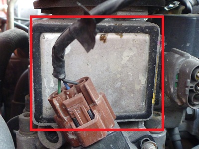
Under here is a lot of strange thingys with a printboard and the lot :
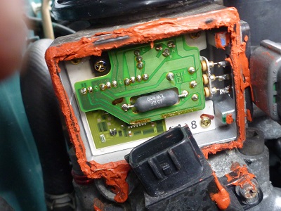
Dont mind the silicone as that was just a emergency roadside fix in the dark… 🙂
What i experienced during the trouble was that the car just went of power and started to act like Kermit the Frog and jumping on and off throttle like nothing i ever seen.
I did some measuring of the contact points and , wham thank you mam , i found some ” cold ” spots in the soldering points at these positions :
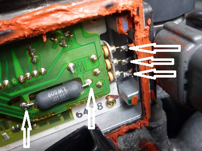
Ran my soldering iron over these spots , cranked the engine and truly , my little darling Micra wass all well again 🙂
Hitting 9000 + rpm all day long and feels like up to the Power like it used to have , without any hesitating at all.
Have been thinking about why this has happened. ?
Could it be my DIY ultra hard engine mounts that has in retunr given off some vibrations so that the soldering points just went bad ??
The engine is being hammered all the way up to more than 9200 RPMs at tracks. Could there be strong resonances in the inlet manifolds killing the soldering points ?
The problem occured almost always under hard usage and when the engine was at its warmest so probably the soldering points just expanded to much at these conditions and giving an erratic reading of the current going through them at any given moment messing up the ECU`s chance of doing its job.
I dont realy know. All i do know is that problems solved , case closed and Maxi boy is putting the pedal to the metal again with the stuff here :
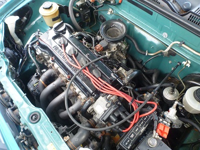
YES , it does run without a filter at the track and YES i do love the sound of it 🙂
Will post some pictures of the MAxi at the dragraces soon 🙂
________________________________________________________________________________-
The Maxi Micra participated on its first Street Legal ever now in April here in Norway.
Here it is proud among mega hp cars 🙂
( Of course it was driven to the race as it is everyday as a working car )

Here it is in the starting line up just about to race :

Quite scary to be amongst so many mega-hp cars and a huge crowd of people who are eager to see anything else than a puny Micra….gulp !
Hitting it to more than 9000 rpm over and over and over again all day long :
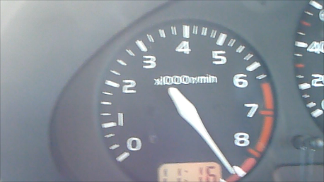
Poor little Micra 🙂
Well , i did my best and wouldnt You know i came all the way to the finals.
Here is some action shot from the final against a angry beast of a pick-up of all things :


Even if i had a good start i lost the final , but only by,,,was it 7 houndreths of a second 🙂
Anyways , i got a nice something to remember it all :
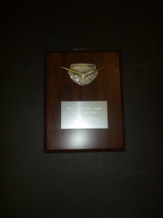
And the car never stood me down , overheated or anything else.
FINAL MOMENT :
The day is here , i have to let the Maxi Micra go,,,buhuu !
With my very busy days there are not enough time to have as many cars as i do today.
This little buddy of a car is now sold and congratulations to the Young enthusiast who bought it to have some fun with.
I will always cherish and remeber all the incredible feedback , learning and fantastic FUN this little car gave me.
It is rare to find a project that can evolve like the Maxi Micra did.
Even rarer is it to know the fact that this car worked perfectly in all the years that i had it and used it on either street , dragracing , autoslolam og tracks driving !
I will like to thank all the people who has taking interest in or helped out with the MAXI MICRA project during the years of different stages of progress.
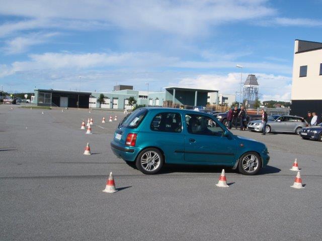


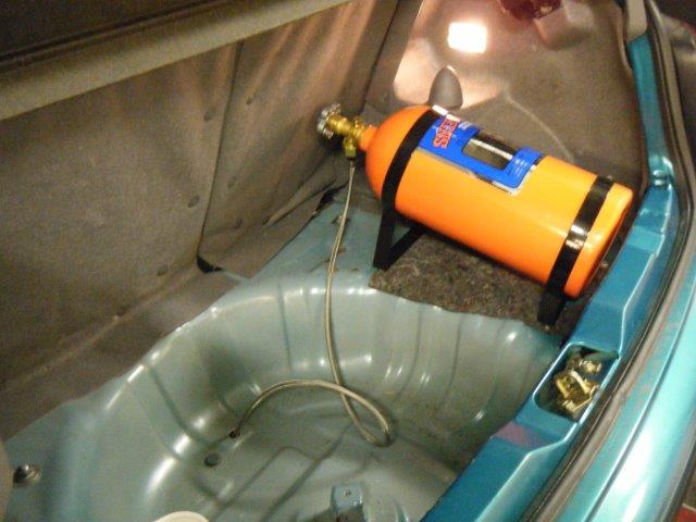


We will never forget You 🙂


 del på